Light Installation
Mounting to Hardtop
- Determine where the light is to be placed.
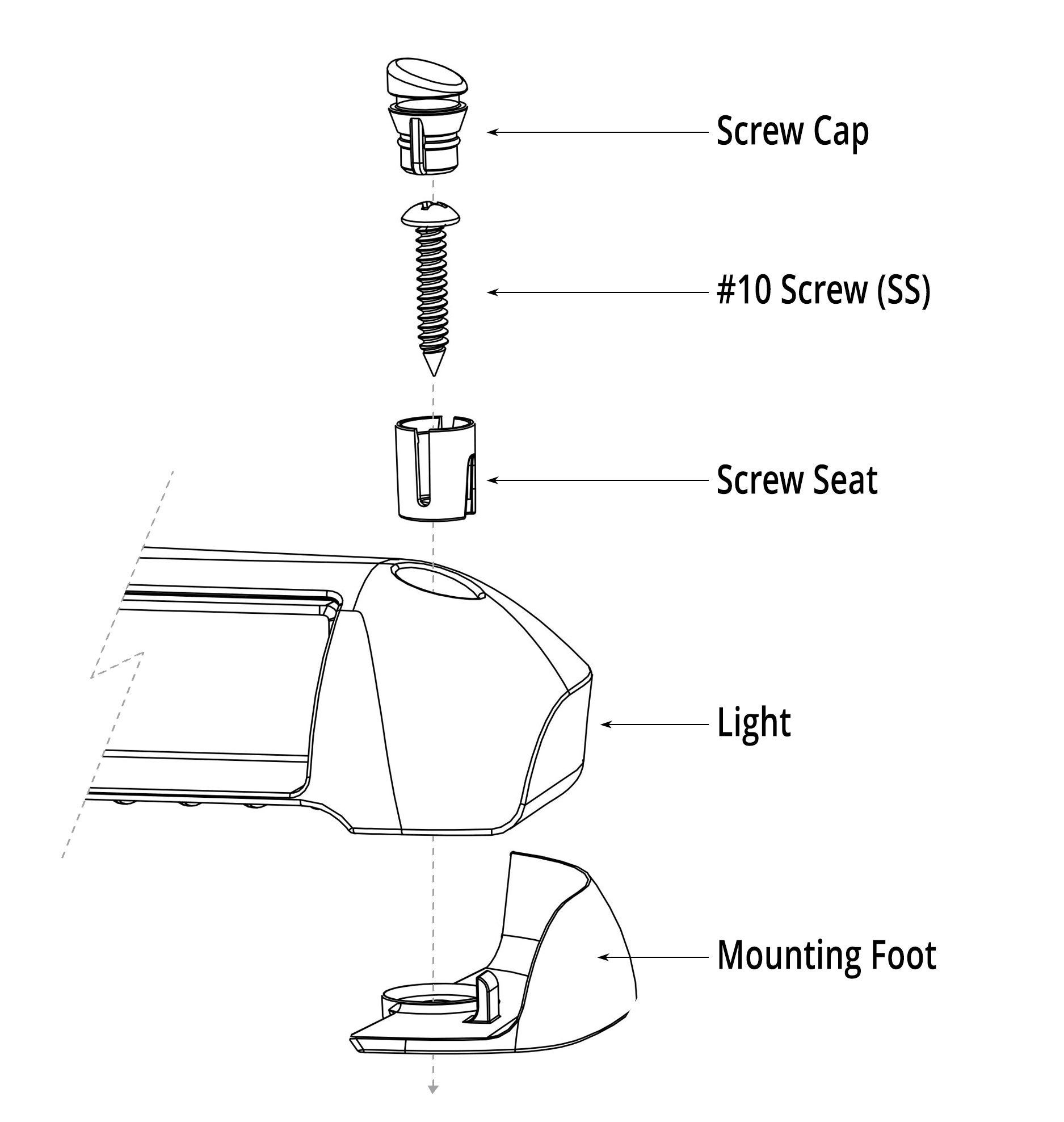
- Place the Razor light bar on the mounting surface. Do not drill any holes at this time.
- Run temporary power and ground to the Razor light bar. Be sure to connect (splice) the Orange internal relay wire to the Red (positive) wire and connect both wires to power (for light placement only).
- Move the lightbar forward or aft to minimize bow glare (watch video).
- Before drilling into the surface, ensure you are not drilling into an area that may have structural support or existing wiring. You should contact the maker of your vessel’s hardtop/t-top to assist with the location of any existing wiring.
- Once a location has been determined, mark the location of the light, disconnect the light from the power, and drill pilot holes for the mounting screws. Screw pilot holes should measure 16” apart. (Drill into fiberglass video link here).
- Drill the two pilot holes for the mounting screws and the hole for the power wires. You may want to install a waterproof grommet (not supplied) where the wires enter the mounting surface.


3-Wire to Switch Wiring


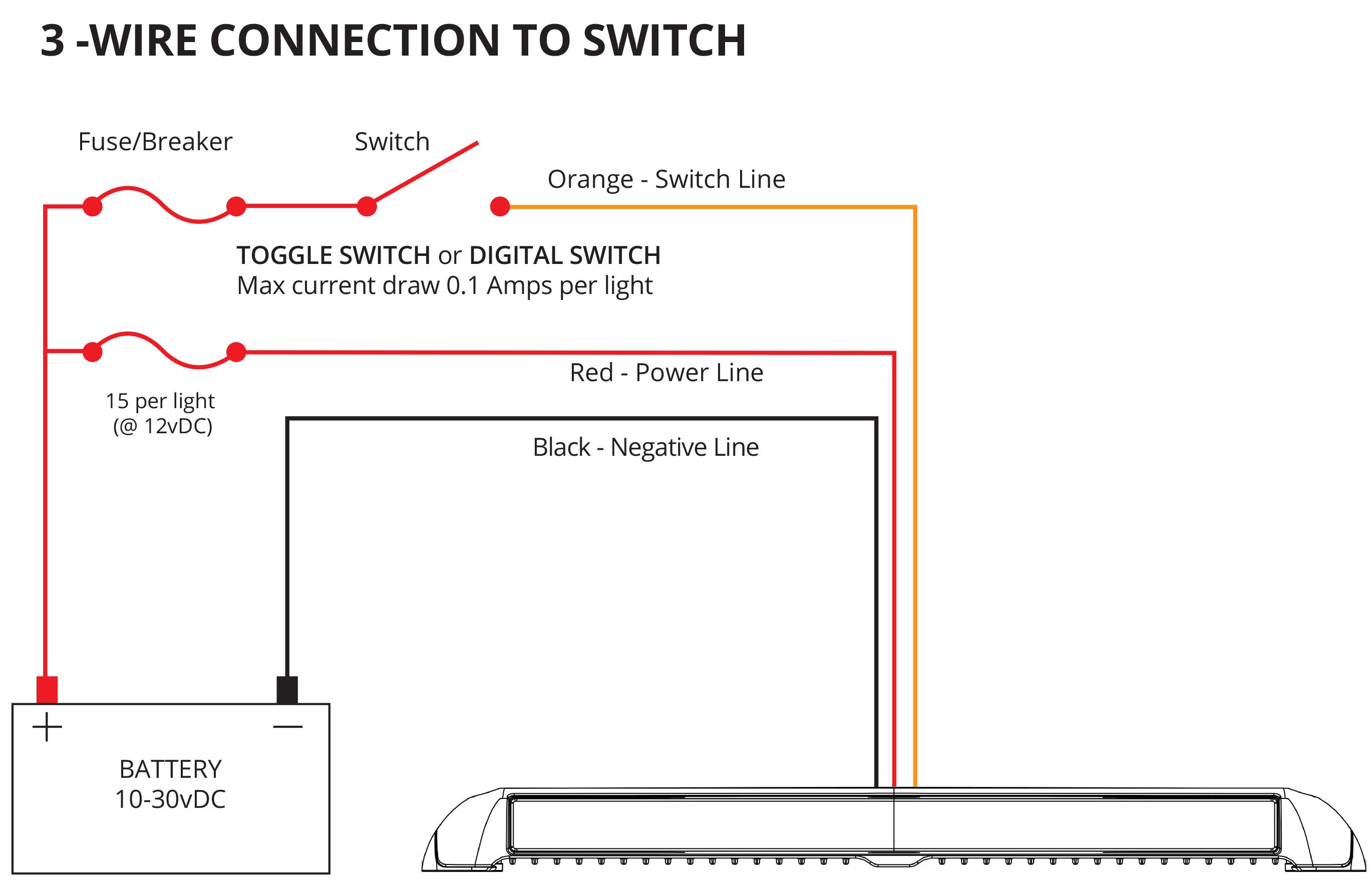
Wiring recommendations –Use ABYC standards to calculate wire size based on the length of the run. If installed as a 3-Wire configuration, the orange wire carries less than 1A of power, and typically, an 18AWG wire can be used. The orange wire of the Razor light bar is the internal relay of the light and also sends commands from the Poco digital lighting control system (if installed).
TIP: To minimize electrical noise and interference, running the positive (red) power and ground (black) return together for as much of the wire run as possible, ideally inside a jacketed cable, is recommended. Avoid loops and coils of the wiring.
- Ensure that the circuit you are connecting to has no power. You should turn off your house battery and test to ensure the circuit is not energized by using a multimeter before continuing.
- Run a marine grade 3 conductor wire from the light to your switch and power source. The red wire will connect to constant power after the house power kill switch, the black to common ground, and the orange wire to the normally open side of a switch. You should install a 15A fuse on the red wire on a 12vDC system (7.4A @ 24vDC). View wire gauge reference chart HERE.
- Connect the wires from the light to the new wire run and follow ABYC standards. Ensure that the wires are crimped correctly, and use a heat gun on the heat shrink of the butt splice connectors.
- Verify the switch is a Single Pole Single Throw (SPST) switch; it has the appropriate Amp rating and is connected to house power through a properly sized fuse. Recommended switch size for a 3-wire installation is 1A (minimum) switch.
- Turn on house power and test the new Razor light bar.
Light Operation
How to Dim the Razor Light Bar
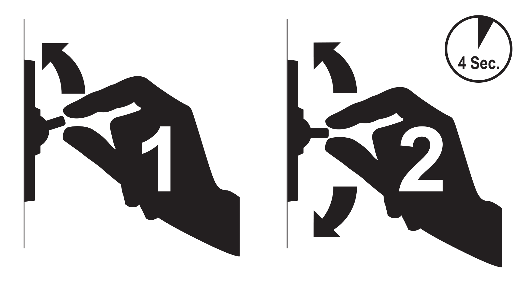
STEP 1: First turn the light on, it will begin in a low power mode and over the course of 4 seconds, the light will ramp up to full brightness of 10,000 lumens.
STEP 2: If you interrupt the ramp-up sequence with a quick off/on toggle of the power switch, the light will hold at that lower intensity level.


TTP (Timed Toggle Protocol)
For more information on the built-in TTP technology, check out the video.


