
Poco - Installation
All installations of the Poco Digital Lighting Control Module should be conducted by a certified professional.

Select Category
Mounting
NOTICE
POCO should be mounted in a location that is not exposed to extreme temperature conditions. This device is rated for operation at ambient
temperatures between 0 F (-18 C) and 120 F (50 C) and is sealed against water ingress per IP65 standards. To prevent standing water, it is
recommended to mount the POCO device on a vertical surface protected from continuous water exposure.
- Using the included hardware, you can surface mount the device close to a breaker panel or fuse block.
- Pre-drill mounting holes with appropriately sized bit depending on the material. Typically a #32 (.116 inch) or 3mm bit can be used for
pre-drilling for the #6 self tapping screws. - Ensure screw holes do not interfere with anything on the opposite side of the mounting surface.
- The location must allow room for routing, the connection of all cables, visibility of LED indicators and access to depress the reset button.
Connections
SUPPLY
Poco must be powered with a 10-30 VDC supply independently fused with a 3 Amp ATC blade fuse or equivalent (Not Provided). Connect the red
power wire to the positive + battery terminal and connect the black wire to the negative - battery terminal. The orange wire can be used for remote
powering of POCO when connected to compatible devices that have a low current output. In cases where remote switching is not used, connect
red and orange power wires together to enable power to the device.
INPUTS
Notice: POCO is designed to switch DC voltages between 10 and 30 volts. Switching ALL AC line voltages or DC voltages higher than 30V is not
permitted and failure to adhere to the input voltage requirement can cause serious injury and death.
OUTPUTS
Each channel is capable of switching a 10 Amp load powered within 10 and 30 VDC. POCO comes with 16 inches (400 mm) 14 AWG wire for each
channel input. Use appropriately sized and sealed crimp terminals to connect with each channel load. See System Design Considerations for
further information on lighting system architecture.
WIRED NETWORK
In order to use the 10/100 Base T network connection for communicating, the POCO device must be connected with a standard ethernet cable
(not included) to a device that acts as a DHCP server. Most MFD manufactures have a DHCP server built into the touch screen and supply
multiple network ports for interfacing with networked devices. If all network ports are used for other system components, a network switch must be
used to split the network traffic between two or more networked devices.
System Design Considerations
In most cases, channels should be designated either a Lumitec PLI channel, standard PWM dimming channel or standard ON/OFF channel.
Lumitec PLI controlled lighting reaches its fullest potential when this rule is followed. Lumitec PLI lighting has the ability to create “virtual circuits” where lighting on each PLI channel can be addressed with commands specific to each clan of lights. For example, SeaBlazeX2 or Typhoon lights can be attached to the same channel as Lumitec Mirage lighting and Caprera2 lighting as well as other clans of lights. Because each are digitally controlled over the two power wires you are able to communicate with light clans independently as if they were setup on multiple circuits.
QUICK TIPS:
- Lighting that is not PLI enabled on a channel that also has PLI enabled lights will stay in the ON state without dimming control, even when other lighting is sent PLI commands. This works well for situations where you want to connect a non-PLI Aurora Dome Light to the same circuit as PLI enabled lights. This setup will only work if the attached non-PLI lights have low internal capacitance or a series diode. Lumitec lights that will work in this configuration include Courtesy and Accent lighting as well as the Touch Dome Light and Aurora Dome Light.
- If PWM dimming control is being used on a channel, PLI enabled lights on that channel will respond as standard lights without digital color control
- PWM dimming control is not compatible with some loads such as relays or inductive loads. For these situations, ensure all commands sent to these commands are ON/OFF only commands (see UI setup for further information)
Phyisical Switches
To connect physical switches to your Poco Module it is recommended you use a Pico S8 Module. The below wiring diagram illustrates how to incorporate the S8 module into your Poco wiring.
Note: For other wiring options that do not use a Pico S8 Module please contact our Technical Support for assistance.

Fig. 1: Use of a single channel to control multiple light types within the lighting system

Fig. 2: Use of different channels to allow isolated control of a set of similar light types within the system

Fig. 3: Use of different channels to allow isolated control of PLI and PWM lighting

Use of a Lumitec Pico S8 module to allow POCO to read the state of mechanical switches and send corresponding digital commands to lights.
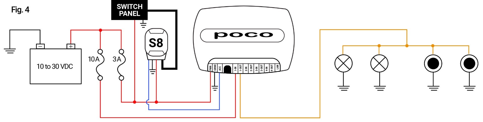
Fig. 5: Use of an SPST switch on a channel to allow for redundant mechanical control of a set of lights within the system allowing for standard Lumitec TTP control or Poco digital PLI control.
Note: POCO will need to be configured with startup commands to turn on all 4 channels by default. Refer to "Startup Menu" under Maintenance section.

Fig. 6: Use of an SPST switch on each channel to allow for standard Lumitec TTP control as well as digital PLI control (non-redundant) Note: POCO will need to be configured with startup commands to turn on all 4 channels by default. Refer to “Startup Switch” under Automation section.

Fig. 7: Use of an SPDT switch prior to all lighting circuits to allow for redundant mechanical control of entire lighting system with one switch.
